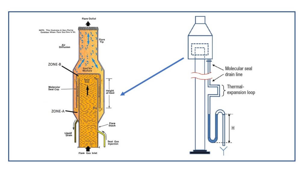
Molecular seals can be used to minimize purge gas rates3. Hence a provision of a drain connection is needed to.

Buoyancy Seal And Velocity Seal For Flare Stack Enggcyclopedia
Molecular seal is an unfortunate name given to a flow restriction installed in a flare stack to minimize the amount of purge gas required.
. Actually the hydrocarbon acts like a seal and prevents the air to ingress into the flare stack and makes a. Value of at design flare release at any location where personnel are continuously exposed. These are generally used in flare systems for gas plants and others where freezing is an issue for seal pots and mol sieves.
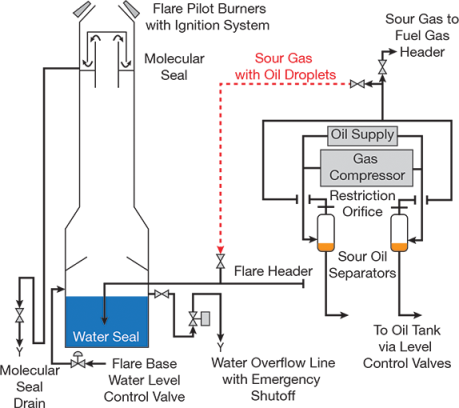
However fluidic seals require more purge gas than molecular seals. The large quantity of gas vented after the compressor tripped blew the oil in the molecular seal out of the flare and it ignited and formed fireballs. 2 The design principle for seal liquid separation tank 21 The description of flare system The flare system consists of the main torch head and acidic flare tip molecular seal seal liquid separation tank flare tower fuel gas line nitrogen line instrument air.
Maximum continuous-flare design is based on. This invention is an improvement over the conventional molecular seal used for the purpose of preventing the reverse flow of air into the top of a flare stack system upon cessation of flow of the lighter-than-air waste or dump combustible gases. The seal is normally flanged between the flare tip and stack and is designed to prevent air from entering the flare system.
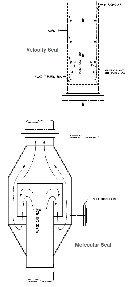
Molecular seals depend on the density difference between air and hydrocarbon gas. This diffusion type seal is theoreically the ultimate purge reduction device and is effectively a pressure vessel installed just below the flare tip. A continuous stream of purge gas is required for proper functioning of the gas seal but the amount of purge gas is much less than would be required without the seal.
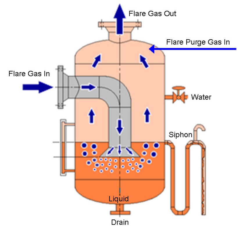
Velocity seal standard on all Encore Combustion flare tips. In design or manufacturing processes are very important parts of the device. As indicated in figure-1 liquid seal at the flare stack base is essentially a cylindrical volume of liquid into which the gas inlet to flare stack is dipped.
Extends flare tip life by minimizing burn back. Every change introduces potential process safety hazards and needs to be evaluated by the PHA team. The molecular type seal forces the purge gas to make two U turns forming a seal because of the different molecular weights.
Light gas is trapped at the top of the U-tube. A flare tip lifting davit DESIGN FEATURES Flare stacks are designed to dispose of flammable gases safely by ensuring the combustion of these gases at the exit of the stack flare tip. The venturi is a series of baffles like open-ended cones in appearance mounted with the flare tip.
Flare design needs to take into account the low relief flow. Molecu-lar seals require a continuous stream of purge gas but the amount of purge gas is less than would be required without the seal. The flare vendor will have to provide details on design options and required purge flow.
This volume allows the flow of flared gas from inlet pipe to. To eliminate the need for a seal drum Molecular or velocity seals Header end and emergency gas purge Flare risers tips and associated hardware fuel gas ignition steam or air Associated monitoring and safety systems including infra red monitors. But much higher gas exit velocities are needed to avoid the burn back of the flare tip.
The most commonly used type of igniter is the flame-front. The Molecular Seal AFS Series is located just below the flare tip and has been designed to. The seal is a gas inversion device causing the gas normally flowing in an upward direction to be turned through 180 degrees in the original.
Molecular seal complete with drain connection inspection port. Long term trouble free operation will save money and time. DuhonGATE Chemical 27 Jun 08 1751.
They also protect gas processing equipment from. Flare Tip Molecular Seal. Schematic diagram of Molecular seal Drum the baffle to seal diameter ratio should not be more than 075 when hydrocarbons are burned in the flare 289.
A cylindrical chamber or housing surrounds vertical pipe sections which are parts of the flare stack system. Molecular seal and water seal drums are the accessories of a flare system that protects the stack from flame front or flash back. The main advantages of fluidic seals are that they are smaller less expensive and weigh less and thus have less structural load on the flare stack than molecular seals.
The purpose is to minimize flare gas purge rates which would otherwise be large and create velocity conditions at the tip that will minimize tip flame impingement and damage of the flare tips. The team should understand the design basis of all flare system parts and. Also known as flare stacks flare tips molecular seals are elevated vertical conveyances found in oil gas wells rigs refineries chemical natural gas plants and landfills.
The Fluidic Flare Upper Multi Baffle Fluidic Seal and Conical Windshield design has proven its effectiveness since 1982. To prevent air ingress the flare included a water seal at the base and a molecular seal at the top. Figures - uploaded by.
Reduced purge gas will reduce environmental emissions as well as operating cost. Liquid seals at base of flare stack. They are used to eliminate waste gas that cannot be otherwise used or transported.
To ensure ignition of flare gases a continuous pilot with a means of remote ignition is recommended for all flares. Buoyancy seal normally reduces purge-gas velocity requirement through the tip to 0003 ms. Moleculare seals work based on the diference between the density of the air and hydrocarbon mixture.
ABSTRACT OF THE DISCLOSURE An improved molecular seal for installation in a flare stack system designed for burning of waste gases of lesser density than air and for installation at an intermediate point in the flare stack. 24 144 610 3658 mm Standard Materials. One drawback of using a buoyancy seal is possibility of liquid accumulation in the bottom of the outer cylinder.
Depending on stack location riser design. Purge flow is required to prevent air ingress into the flare stack. The molecular seal included a drain line with a U-seal and isolation valve at the bottom.
It is undesirable to have a flarestack filled with a. Both seals provide significant savings in operating costs. The Molecular Seal is located just below the flare tip and has been designed to prevent air ingress to the flare riser thus preventing the formation of an explosive mixture in the system.
The seal has a housing of larger cross-section than that of the flare stack the housing being closed by plates at both ends with an outlet conduit sealed.
Manage Change To Flare Systems Aiche

Buoyancy Seal And Velocity Seal For Flare Stack Enggcyclopedia
Flare System Part Flare Process Flare Drums Flare Seals The Piping Talk
Purge Reduction Seals Velocity And Molecular Seals Encore Combustion
Flare System Part Flare Process Flare Drums Flare Seals The Piping Talk
Manage Change To Flare Systems Aiche
2
Schematic Diagram Of Molecular Seal Drum The Baffle To Seal Diameter Download Scientific Diagram
0 comments
Post a Comment